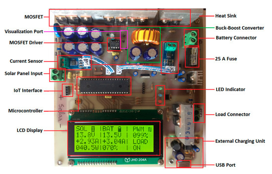
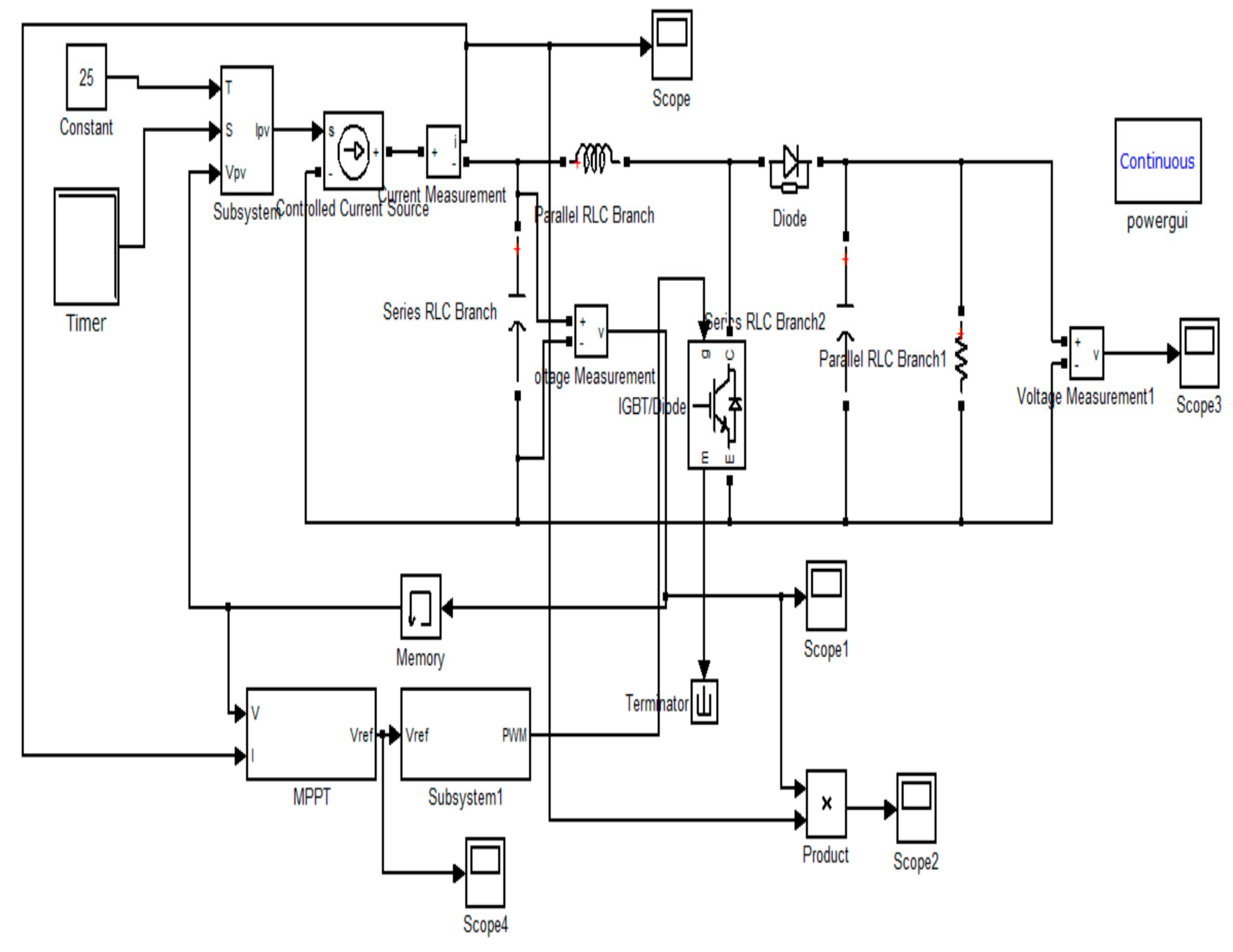
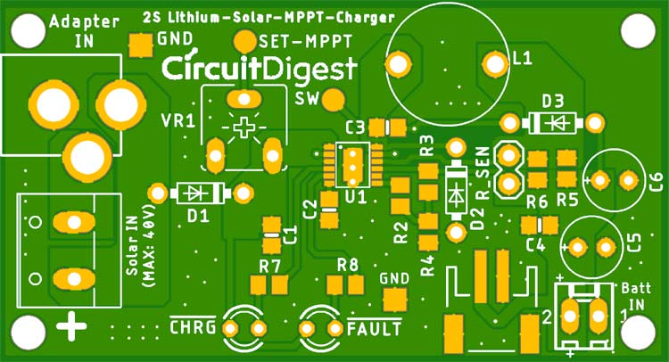
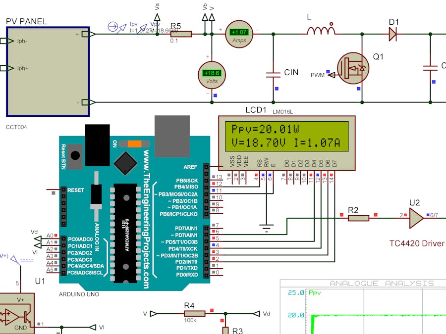
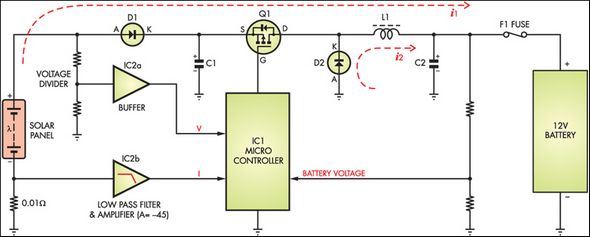
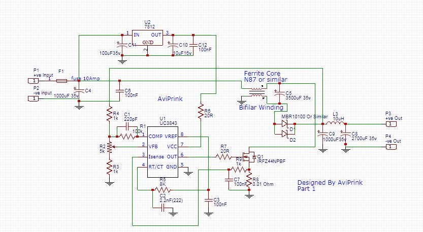
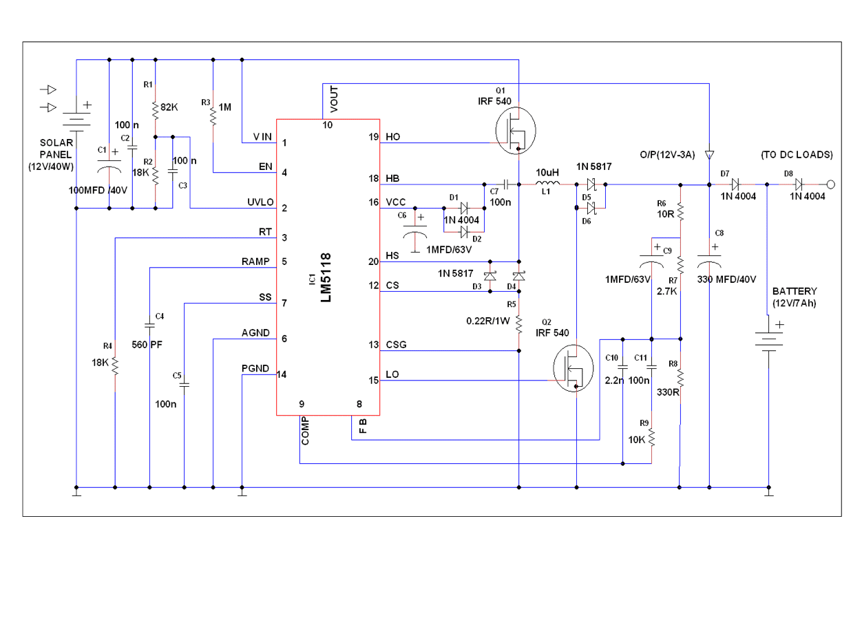
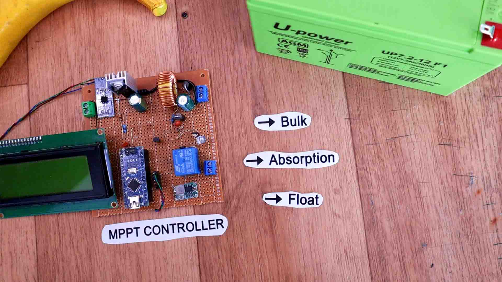
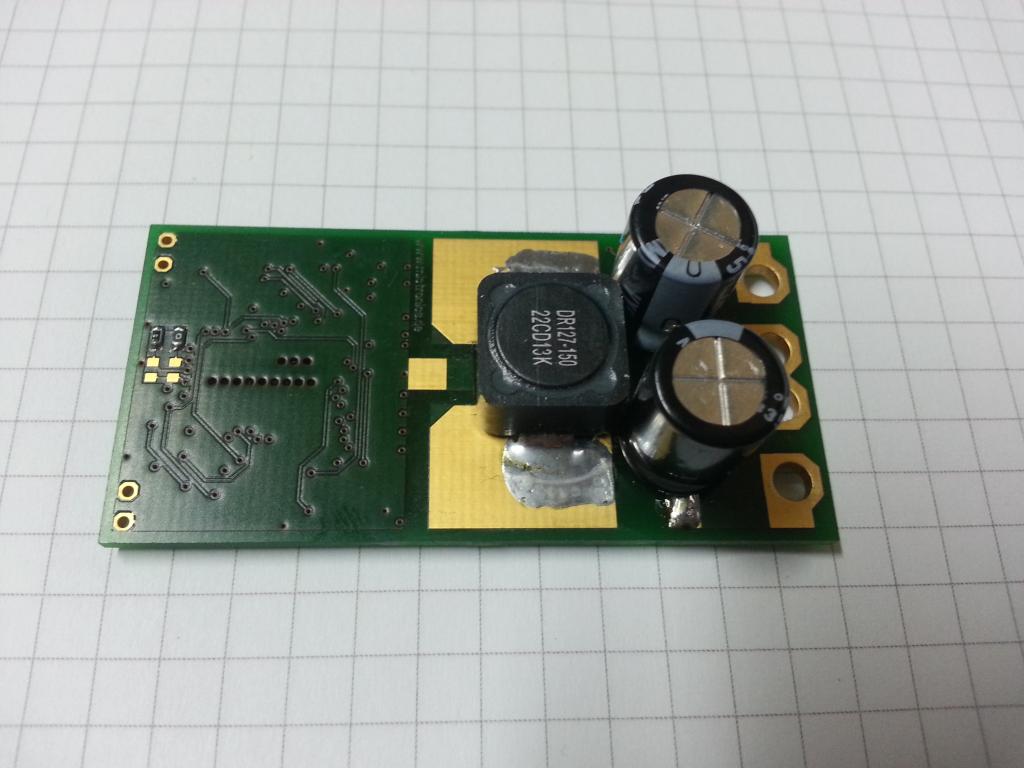
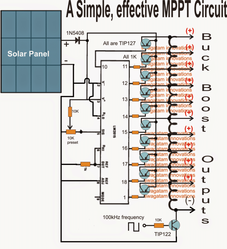
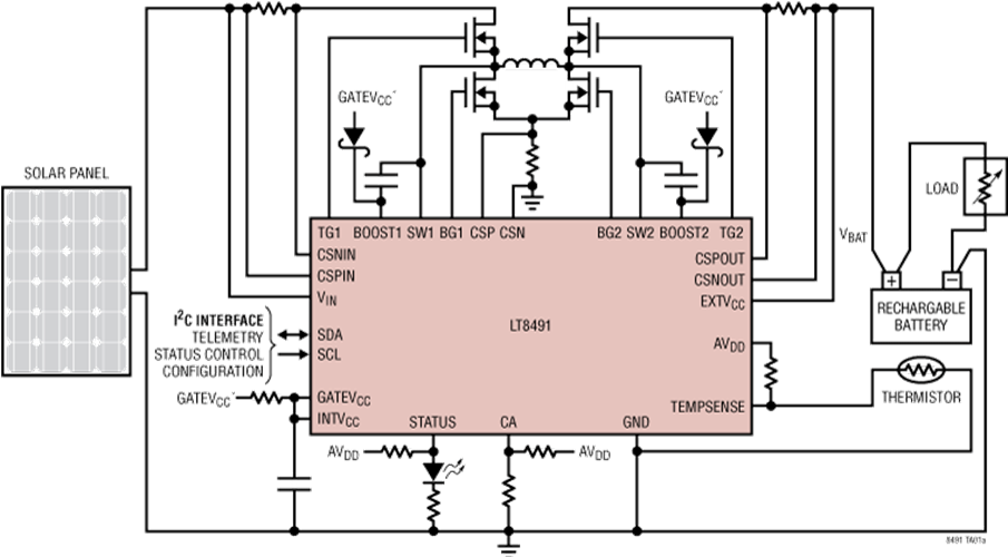
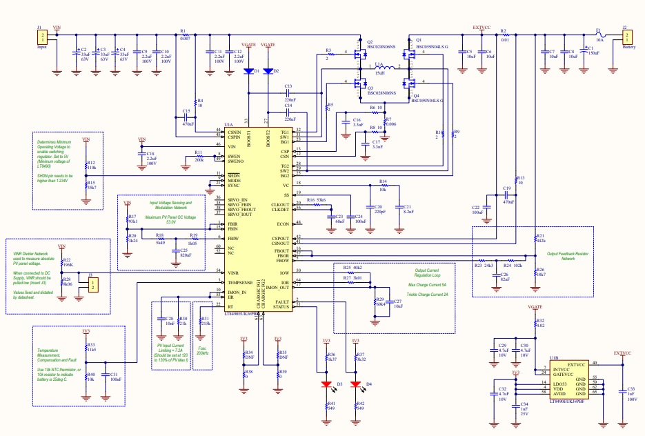
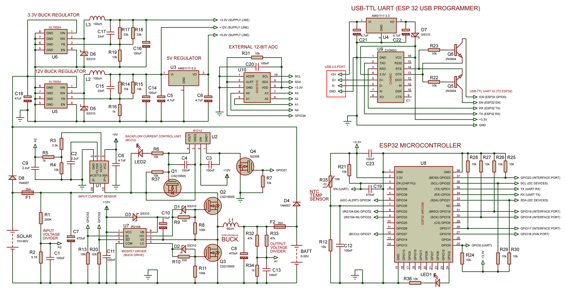
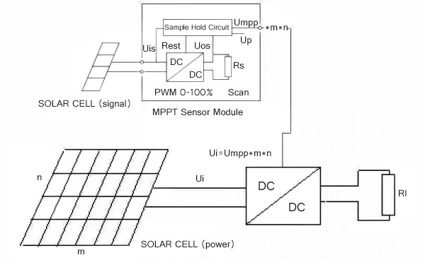
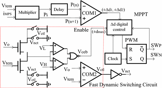
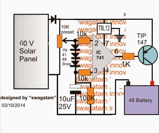
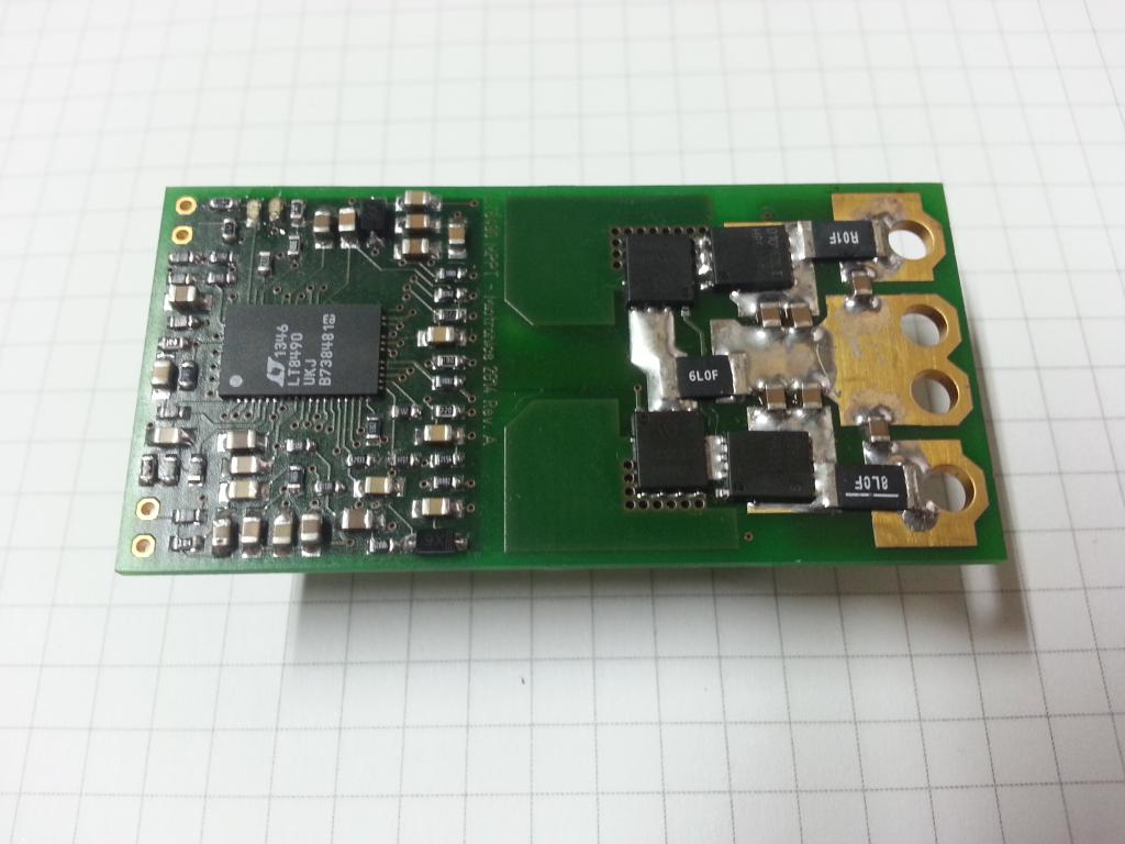
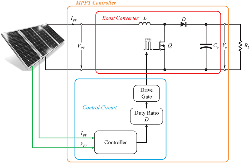
This circuit works with the concept of Maximum Power Point Tracking (MPPT) to increase the efficiency of the solar photovoltaic system The output power of a PV panel is a
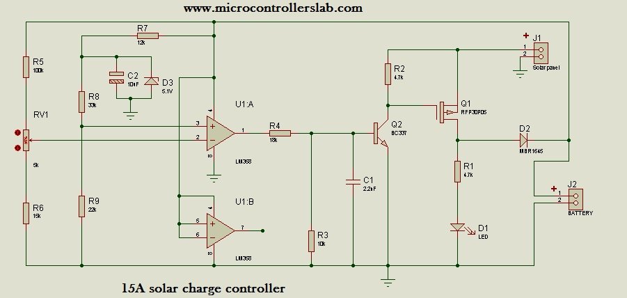
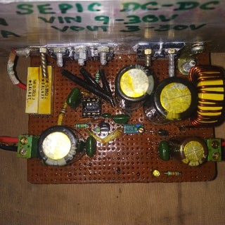
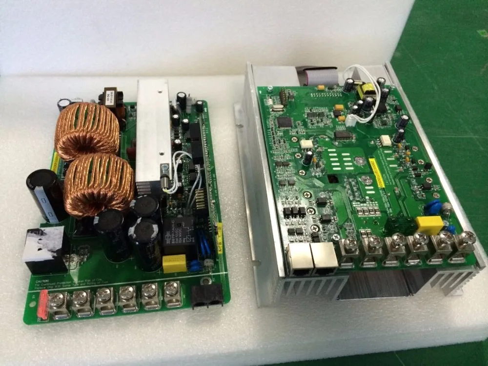
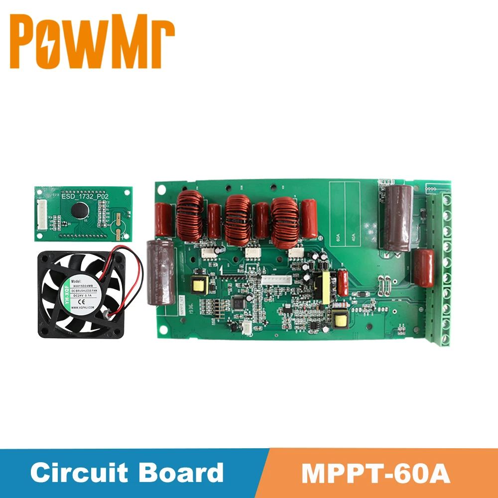
Mppt circuit diagram-MPPT (Maximum Power Point Tracking) as the name suggests this algorithm tracks the maximum available power from panels and varies the output parameters to sustain the condition Step 6DIY Solar Boost Converter with MPPT Charge Controller This is a simple solar boost converter and voltage limiter circuit that charges a 12V battery from a 6V solar panel It also demonstrates
Mppt circuit diagramのギャラリー
各画像をクリックすると、ダウンロードまたは拡大表示できます
 |  |  |
 |  |  |
 |  | |
 | ||
「Mppt circuit diagram」の画像ギャラリー、詳細は各画像をクリックしてください。
 |  |  |
 |  | |
 |  |  |
 |  |  |
「Mppt circuit diagram」の画像ギャラリー、詳細は各画像をクリックしてください。
 |  |  |
 |  | |
 |  |  |
 | 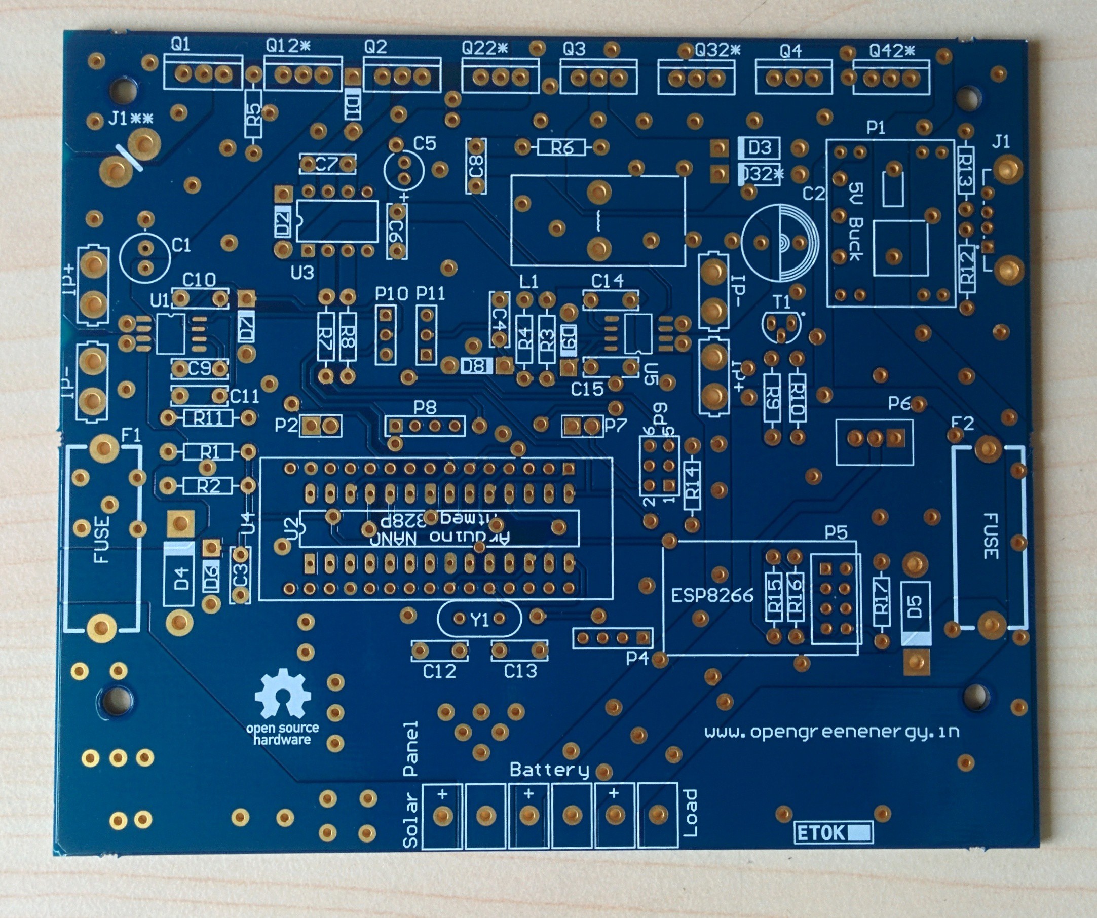 |  |
「Mppt circuit diagram」の画像ギャラリー、詳細は各画像をクリックしてください。
 | 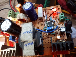 | |
 | 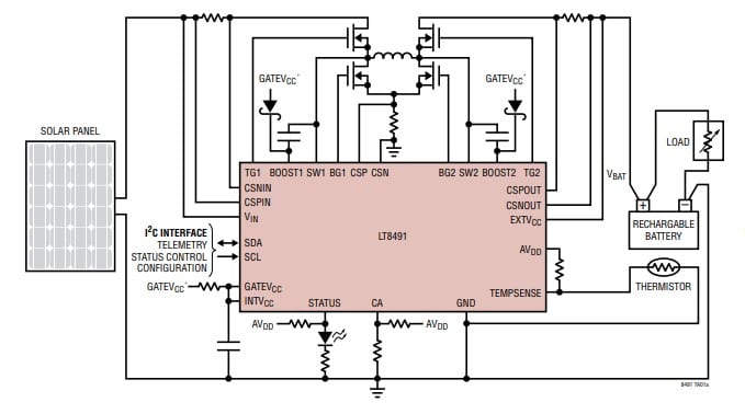 |  |
 |  | |
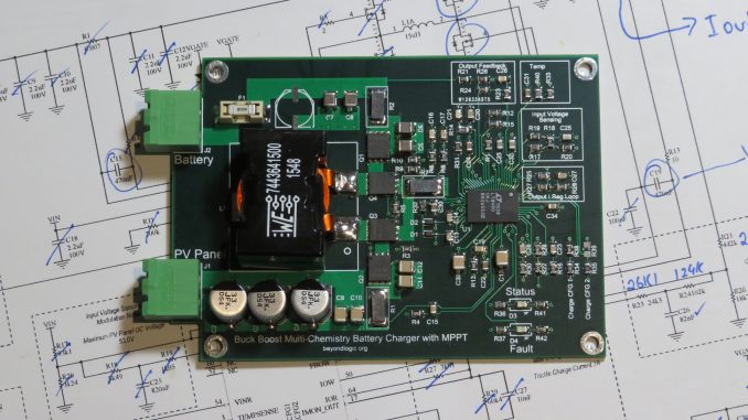 |  |  |
「Mppt circuit diagram」の画像ギャラリー、詳細は各画像をクリックしてください。
 |  | |
 |  | |
 |  |  |
 |  | |
「Mppt circuit diagram」の画像ギャラリー、詳細は各画像をクリックしてください。
 |  |  |
 |  | |
 |  |  |
 |  |  |
「Mppt circuit diagram」の画像ギャラリー、詳細は各画像をクリックしてください。
 |  | _5kneItTeWY.png) |
 |  | |
 |  |  |
 |  | |
「Mppt circuit diagram」の画像ギャラリー、詳細は各画像をクリックしてください。
 |  |  |
 |  |  |
 |  |  |
 |  |  |
「Mppt circuit diagram」の画像ギャラリー、詳細は各画像をクリックしてください。
 |  |  |
 |  |  |
 |  |
Working of MPPT Solar Charge Controller The solar panel voltage 176V at 76A is converted down by MPPT to match the 12V battery Thus, the battery gets 12V at 108A making the total powerDownload scientific diagram PV system with MPPT circuit from publication Highly efficient maximum power point tracking using DC–DC coupled inductor singleended primary inductance
Incoming Term: mppt circuit, mppt circuit diagram, mppt circuit board, mppt circuit explained, mppt circuit breaker, mppt circuit diagram pdf, mppt circuit arduino, mppt circuit schematic, mppt circuit charger, mppt circuit diy,


0 件のコメント:
コメントを投稿